Process intensifier AVS-100. Vortex Layer Device
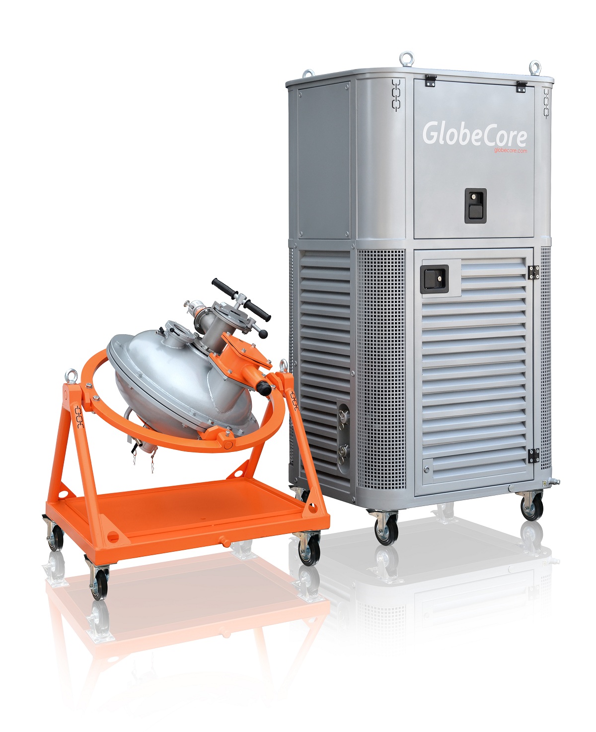
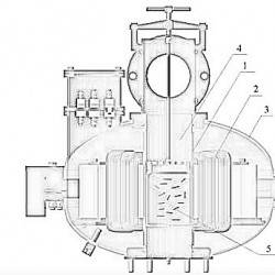
Fig. 1. Electromagnetic vortex system:
1 – protective bushing; 2 – inductor of rotating electromagnetic field;
3 – inductor body; 4 – non-magnetic material work operating chamber;
5 – ferromagnetic elements
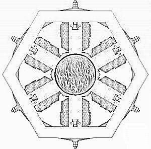
Figure 2. A photo of vortex layer (1000 frame per second camera)
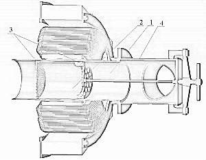
Fig. 3. The chamber of AVS for liquid phase processes:
1 – chamber; 2 – bush; 3– strainer;
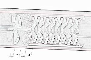
Fig. 4. AVS chamber with knives:
1 – knoves; 2 – chamber; 3– mesh filter; 4 – bush.
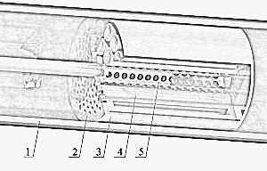
Fig. 5. AVS chamber with tubes:
1 – chamber; 2 – mesh; 3 – bush; 4 – tubes; 5 – filter tube.
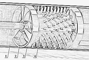
Fig. 6. AVS chamber with rotor:
1 – chamber; 2– bronze bushings (lubricated and cooled by the processed liquid); 3 – lid; 4 – rotor