
Treatment of industrial waste water is one of the most important stages of any production process. Besides, environmental safety is not only a matter of preference, but a requirement in our times. In this page you can find information on industrial applications of the vortex layer device in waste water treatment and the existing process arrangements of implemented devices.
Removal of hexavalent chrome and other heavy metals
The nature of the vortex layer used for treatment of waste water containing hexavalent chrome and other heavy metals allows to radically reduce reagent consumption, achieves a more complete purification and makes the process continuous.
Ferromagnetic elements in the active zone of the AVS device, in the electromagnetic field, intensively mix the reagents entering the active zone. The shock and friction causes pulverization to colloid degree of dispersion. The colloid metal is a good reduction agent.
Simultaneously with the formation of colloid metal in the process of ferromagnetic element dispersion, the electrolysis of water in the vortex layer generates hydrogen. Both factors play a significant part in reduction of hexavalent chrome and other heavy metals in the waste water. This capability of the vortex layer significantly reduces the consumption of ferric sulfate for reduction of hexavalent chrome, and even achieve complete reduction of hexavalent chrome and other metals in the waste water due to just the colloid metal and the emitted hydrogen.
Take a look at real researches, more information on the video
To demonstrate the unit, we will purify a sample of chromium containing waste water from electroplating production
Acid and heavy metal content before processing:
pH: 1.75
Fe /iron/: 9.7 mg/liter
Cu /copper/: 19.29 mg/liter
Ni /nickel/: 5.8 mg/liter
Cr+6 /hexavalent chromium/: 19.08 mg/liter
The reduction agent used is ferrous sulfate, FeSO4.
To reduce hexavalent chromium to trivalent chromium we will increase acidity to 7.5 pH by adding lime milk, Ca(OH)2.
The processing time is 3 seconds. In a stream, when the vortex layer is engaged, the processing takes fractions of a second.
The intensive mixing of the reagents and the influence of the electromagnetic fields, as well as dispersion of the compounds leads to better dispersion of the metal hydroxides, than that in mechanical mixing devices.
Curiously, increase of sediment dispersion does not slow its setting. On the contrary, sedimentation of solid phase particles in the AVS occurs 1.5 – 2 times faster than in a mechanical mixing device. This is due to the intensive magnetic influence on the suspension changing the interfacial tension on the coundary between the liquid and the solid particle.
A most important property of the vortex layer is the fact that the physical and chemical properties of a substance changes after processing, significantly changing the chemical activity of the product.
Using a mechanical mixer device involves equipment with large footprint and significant capital investment. The duration of the cyclic purification process in this method is 30 to 120 minutes.
Using the AVS for purification of waste water from chrome by using chemical reduction in alkaline environment with simultaneous settling of chrome and other metals in the form of hydroxides only requires vessels for ferrous sulfate and lime milk with portioning devices, one AVS device and a filter or a sludge collector.
The results of testing the vortex layer device for decontamination of chrome-containing waste water are as follows.
Table 1
Results of decontamination of chrome-containing waste water in AVS
| Initial concentration of Cr6+, mg/dm3 | pH of the process | Consumption of ferrous sulfate, % of stoichiometric amount | Weigth of the ferromagnetic elements, g | Residual Cr6+ after purification, mg/dm3 |
| 100 | 2 | 100 | 150 | 0 |
| 90 | 0 | |||
| 80 | 0,56 | |||
| 100 | 4 | 90 | 150 | 0 |
| 80 | 0,9 | |||
| 590 | 2 | 100 | 200 | 0 |
| 90 | 0 | |||
| 80 | 0,8 | |||
| 1000 | 2,5 | 100 | 200 | 0 |
| 90 | 0,11 | |||
| 80 | 1,1 | |||
| 200 | 7,5 | 100 | 150 | 0,012 |
| 200 | 9,0 | 100 | 150 | 0 |
| 90 | 0,05 | |||
| 80 | 0,98 | |||
| 750 | 7,5-8,5 | 90 | 200 | 0,1-0,01 |
Table 2
Results of neutralization and removal of heavy metal ions in an industrial unit with AVS
| Initial metal concentration, mg/dm3 |
pH of the process | Consumption of Са(ОН)2, % of stoichiometric amount | Weigth of the ferromagnetic elements, g | Residual metal content, mg/dm3 |
| Fe2+; 3+ = 130,0 | 7,5 | 90,0 | 200 | Fe2+; 3+ – 0 |
| Cu2+ = 50,0 | Cu2+ – 0,12 | |||
| Zn2+ = 45,0 | Zn2+ – 0,063 | |||
| Cd2+ = 10,0 | Cd2+ – 0,07 | |||
| Cr3+ = 120,0 | Cr3+ – 0 | |||
| Fe2+; 3+ = 170,0 | 8,5 | 100,0 | 150 | Fe2+; 3+ – 0 |
| Cu2+ = 40,0 | Cu2+ – 0,018 | |||
| Zn2+ = 28,0 | Zn2+ – 0 | |||
| Cd2+ = 5,5 | Cd2+ – 0,011 | |||
| Cr3+ = 100,0 | Cr3+ – 0 | |||
| Fe2+; 3+ = 250,0 | 8,7 | 100,0 | 200 | Fe2+; 3+ – 0 |
| Cu2+ = 65,0 | Cu2+ – footprints | |||
| Zn2+ = 35,0 | Zn2+ – footprints | |||
| Cd2+ = 2505 | Cd2+ – 0 | |||
| Cr3+ = 350,0 | Cr3+ – 0 |
Simultaneously, industrial purification using mechanical agitation and bubble aeration was performed. Consumption of lime milk in the process was 115 — 120% of stoichiometric amount. Duration of mixing the waste water with the reagent was 15-20 minutes.
Figures 1-3 show comparative dependencies heavy metal removal efficient and clarification of waste water in settling tanks using AVS and mechanical mixers.
To compare efficiency of removing chrome from waste water in industrial conditions, chrome was reduced in a regular reagent process in a reactor with bubble aeration, treatment duration was 15-25 minutes.
Figure 3 shows the comparative data of this test.
The results of industrial use of the AVS in facilities purifying chrome containing waste water, both in acidic and alkaline environment, indicate that the AVS based process offers better purification qualities (below the maximum allowable level of contamination) removing chrome and heavy metals (Fe, Ni , Zn, Cu, Cd), while using 90-100% reagents of stoichiometric amount and significant simplification of purification facilities and their operation, as confirmed by the results of experimental research and the efficiency of the ferromagnetic element vortex layer in the AVS. In the regular reagent process, the consumption of reagents is: 115-120% of precipitation agent (Ca(OH)2, Na2CO3) and 150-175% of reduction agent (FeSO4).
Based on the experiments and the industrial testing of the AVS in the waste water purification process, new processes were offered and implemented in purification facilities of various industrial sites (Fig. 4, 5).
-
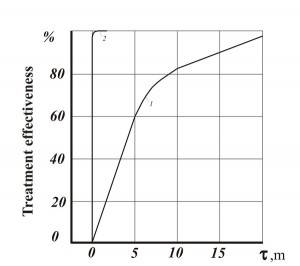
- Fig. 1. Efficiency of waste water purification of heavy metals: 1 – mechanical agitator reactor (consumption of Ca(OH)2 – 115-120% of the stoichiometric amount); 2 – AVS (consumption of Ca(OH)2 –92% of the stoichiometric amount)
-
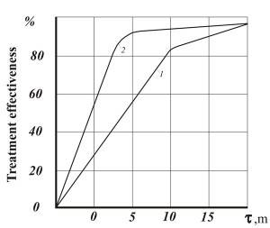
- Fig. 2. Dependency of efficient clarification of waste water in settling tanks after formation of metal hydroxide: 1 – mechanical agitator reactor; 2 – AVS
-
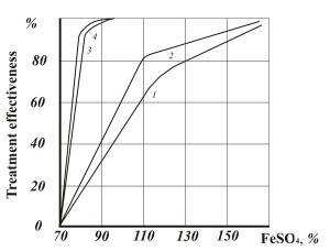
- Fig. 3 Efficiency of hexavalent chrome reduction: 1,2 – in reactor (bubble aeration) with chrome concentration 50 and 100 mg/dm3 respectively; 3,4 – the same in AVS
Figure 4 shows the process diagram of simultaneous purification of chrome-containing and acidic/alkaline waste water, the essence being that the waste water from two sections of the facility flow into two mixing vessels in turns.
When one of the tanks is full and the water is averaged, acid is added to bring pH to 2-3, along with reduction agent (sodium bisulphate). After mixing for 5-10 minutes, the water flows to the AVS. Alkali (Na2CO3) is added to the flow to bring рН to 7.5-9. In the AVS the waste water is processed with the reagents for several seconds, completing the reduction of Cr6+ to Cr3+ and formation of Cr3+ and other heavy metal hydroxides. A possible reduction agent is ferrous sulfate (FeSO4).
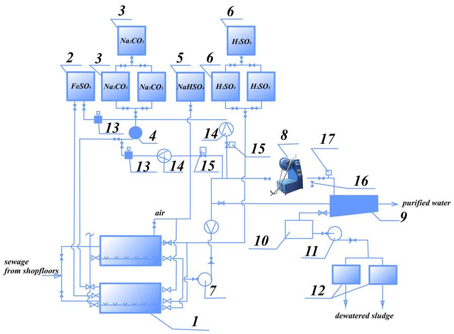
Figure. 4 Process diagram for simultaneous purification of chrome and acid/alkali containing waste water: 1- mixing tank; 2 — reduction agent tank (FeSO4 solution); 3 —Na2CO3 solution preparation tank; 4,7,11 — pumps; 5 — reduction agent tank; 6 — sulfuric acid tank; 8 — AVS; 9, 10 — settling tank; 12 — vacuum filter; 13 — portioning; 14 — flow meter; 15 — reagent consumption regulation valve; 16 — sampling; 17 — pH-meter
Using vortex layer devices in this process improves the purification to the point where contamination is below the maximum allowable limits, reduce reagent us by 1.5-2 times, half the energy costs and reduce purification facility footprint by 10 – 15%.
- Reduction of Cr6+ to Cr3+ in chrome containing water;
- Oxidation of cyanides to cyanates in in cyan-containing waste water (pH 10-11, alkali and oxidant);
- Simultaneous purification of waste water after mixing decontaminated chrome and cyan containing water with alkaline/acidic water.
To removal of salts from the purified waste, a gravel-sand filter, cation and anion exchange filters are used, from which the water goes to clean water tank and back into the process.
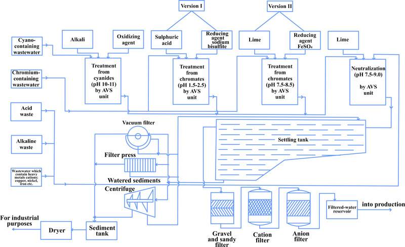
Fig. 5 Process diagram of galvanic plating waste water purification
This method of waste water purification if the most economical, opening wide possibilities of its use in various industries.
Back to Top
Purification of waste water from phenol and other organic contaminants
In most facilities, such water is purified by oxidizing phenol and other organic contaminants by manganese peroxide, sodium or potassium dichromate at 95-100º С. The oxidation process takes 3 to 5 hours, consuming 5 grams of oxidant per 1 gram of phenol.
Using AVS allows to significantly simplify the process, reduce the oxidation reaction temperature to 20-25º С, lower oxidant consumption to 2-3g per 1 g of phenol and reduce the reaction duration to hundredth of a second.
The purification unit with 12 reactors 25 m3 each can purify 400 to 600 m3 of water per day. The method often does not ensure high quality of purification, wit only 75-90% rate of phenol removal.
We have developed a new continuous process of decontamination waste water containing phenol and other organic contaminants using the vortex layer device.
Testing indicated that AVS can ensure good purification of waste water from phenol with lower operation costs than those involved in regular methods.
It was determined that removal of phenol in the concentration of 0.5-10 g/dm3, at acidity up to 5 g/dm3 can be performed by such oxidants as manganese peroxide, sodium or potassium dichromate, potassium potassium permanganate for oxidation time τ = 0.1-2 seconds, at 20-45 ºС to residual phenol content after purification1.2-10 mg/dm3 when using manganese peroxide, 0.2-5 mg/dm3 using potassium dichromate, 0.1-1.0 mg/dm3 potassium permanganate.
The process of removal phenol from waste water using AVS (fig. 6) is simpler in terms of technology and hardware than the current industrial process.
Simultaneous with phenol oxidation, other organic contaminants in the water also oxidize. Formaldehyde content is reduced to 50-100 mg/dm3 (initially 10 g/dm3), methanol – to 2.3 mg/dm3 (initially 6.4 g/dm3), diphenylol propane – to 150 mg/dm3 (initial 4.6 g/dm3).
The following conditions are recommended for purification of phenol-containing waste water in AVS:
- Initial water acidity no less than 3-5 g/dm3;
- Oxidation process temperature 20-45º С (in waste water contains resins, the temperature should be increased to 45-60ºС);
- Oxidant consumption 2.5-3.0 weight parts per 1 g phenol;
- Device processing rate: AVS-100 – up to 10 m3/hour, AVS-150 up to 25 m3/hour.
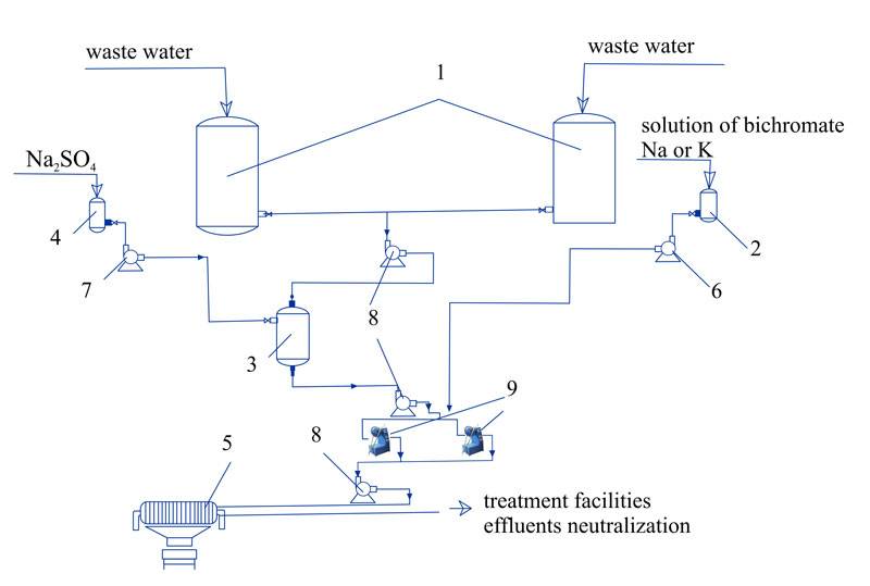
Fig. 6. The process of phenol removal from industrial waste water (recommended): 1 – waste water averaging; 2 – oxidant tank; 3 – oxidation reactor; 4 –Na2SO4 storage tank; 5 – filter-press; 6,7,8 – pumps; 9 – AVS.
Implementation of vortex layer device in the process of phenol removel reduced energy costs by 10 – 15 times, lowers reagent consumption by 1.5-2 times, decreases equipment footprint by 1.5 – 2 times.
Back to Top
Removal of cyanides
The most toxic waste waters are those containing both simple cyanides (with CN—ions) and complex [Cu(CN2)—], [Cu(CN3)-2], [Zn(CN4)-2] etc. Total concentration of simple and complex cyanides varies from 10-15 to 150-300 mg/liter. The most widespread method today is reagent method of oxidation by calcium hypochlorite Ca(OCl)2, hypochlorite lime CaOCl2 or gaseous chlorine.
Most of the cyanide-containing water is purified in cyclic purification units, where the water is treated by the reagents in reservoirs. Larger amounts of waste water are processed in continuous devices.
The reaction occurs in two stages: oxidation of cyanides to cyanates at pH=10÷11.5, followed by cyanate hydrolysis to nitrogen and carbon dioxide at pH=7÷7.5.
Using the vortex layer device allows to oxidize cyanides and decompose them into carbonates and ammonia in one stage in alkaline environment at pH=9÷10.
In the industrial method of purifying cyanide-containing water, the water follows into averaging tank and are pumped into the vortex layer device. At the same time, alkaline agent and oxidizer are supplied to the active zone of the device. pH and cyanide content are monitored by a pH meter and cyan signaler. The water from the device follows to a collector and are mixed with neutralized water from other electroplating facilities.
A 5 – 10% solution of lime or soda is used as alkaline agent, the oxidizer is calcium hypochlorite, chlorine or hypochlorite lime. Oxidizer consumption is 110% of stoichiometric calculation.
Table 3 presents analysis of the results obtained by testing AVS-100 device purifying cyanide-containing waste water at the rate of 12-15 m3/hour.
Table 3
The results of purifying cyanide-containing waste water using AVS-100 vortex layer device
| Initial cyan ion content, mg/liter | Content of cyan ions after AVS processing, mg/liter |
| 8000 | 0.12 |
| 2300 | 0.09 |
| 4320 | 0.02 |
| 50 | 0.02 |
| 62.4 | 0.0011 |
| 34.3 | 0.0014 |
As the data shows, the quality of purification is not related to the concentration of cyan-ion in the initial waste water.
Back to Top
Removal of arsenic from waste water
A pressing problem of mining and ore industry is the removal of arsenic from waste water by precipitating it using iron hydroxide or reduction by Na2S, K2S, FeS2.
The sedimentation process occurs when a ferrous salt, such as FeCl3, forms a soft amorphous sediment Fe(OH)3 in alkaline environment, which has larger active area. As the substance precipitates, it adsorbs and carries away ions of arsenite and arsenate. This is the process of reducing AS5+ to AS3+.
We have run tests using electromagnetic fields in the process of arsenic removal from waste water.
There were two directions of research:
- Precipitation of arsenic compounds as complexes;
- Reduction of arsenic compounds.
The waters used in the tests were taken from production of magnesium, xanthate production and processing of pyrites.
The reagents used were ferrichloride, nitrite concentrate, potassium and sodium sulphide, which are part of xanthate production.
Quality of waste water purification depends on the pH of the media, the amount of reagents and other factors. Therefore, we research the influence of the following factors on precipitation or reduction of arsenic:
- Amount of reagents;
- pH of the environment;
- duration of processing in the vortex layer;
- duration of saturating the researched water sample with oxygen to improve process conditions.
The reagent used to remove waste water from arsenic was ferrichloride in carious weight ratios to the content of arsenic in the water. The exiting industrial process uses 10 times the amount of FeCl3, only bringing arsenic content to the maximum allowable limits.
In the process we used AVS-100 vortex layer device (m = 150 g, τ = 3-5 seconds), and with the consumption of the reagent in the same amount as in the exiting technology, no arsenic was detected in purified water. Using a 5 time excess of the reagent yields the same results, while 3 times excess significantly lowers the concentration from initial 2115 mg/dm³ to residual 116 mg/dm³.
The conditions of the process during the research were changed as follows:
- Loading of the reagent (pyrite concentrate) into the water without prior pulverization in AVS;
- Loading of pyrite concentrate pulverized in AVS (τ = 5-60 seconds, pH = 5-8), and supply of air into the water without processing in the device. The amount ot reagent changed depending on arsenic concentration.
To remove arsenic from waste water of a copper plant using AVS, the reagents used were Na2S, K2S, which are part of xanthate process byproducts.
The parameters of purification process were: τ = 1-3 seconds, pH = 3-4, m = 175 g, concentration of AS5+ in initial water 1.6 g/dm³, acidity 5-6 g/dm³.
The results of waste water purification from arsenic are shown in Table 4.
Table 4
The results of researching arsenic-containing waste water purification in AVS
| Ferromagnetic elements | Concentration of AS5+ in initial water, mg/dm³ |
Reagent consumption, g |
Duration of processing in the vortex layer, с |
Concentration of arsenic in purified water, mg/dm³ |
|||
| weight, g |
length, mm |
diameter, mm |
|||||
| Magnesium production | |||||||
| 150 | 16-18 | 1,6 | 2115 (pH = 7-8) | 10 times FeCl3 | 5 | 0 | |
| 150 | 16-18 | 1,6 | 2115 (pH = 7-8) | 5 times FeCl3 | 1-5 | 0 | |
| 150 | 16-18 | 1,6 | 2115 (pH = 7-8) | 3 times FeCl3 | 1-5 | 0,9-0 | |
| 150 | 16-18 | 1,6 | 2115 (pH = 7-8) | 3 times FeCl3 | 5 | 1,0 | |
| 175 | 16-18 | 1,6 | 35 (pH = 7-8) | Pyrite concentrate, 65 g | 60 | 28 (no bubble aeration) 0(with bubble aeration) |
|
| 175 | 16-18 | 1,6 | 35 (pH = 7-8) | Pyrite concentrate 3.5 g | 60 | 24 (no bubble aeration) 0(with bubble aeration) |
|
| 175 | 16-18 | 1,6 | 35 (pH = 7-8) | Pyrite concentrate 10.0 g | 60 | 0,05 (no bubble aeration) 0(with bubble aeration) |
|
| 175 | 16-18 | 1,6 | 35 (pH = 5-6) | Pyrite concentrate 0.65 g | 5 | 2,0 (no bubble aeration) 0,04 (with bubble aeration) | |
| Xanthate waste water | |||||||
| 175 | 16-18 | 1,6 | 2000 (pH3) | 7,0 Na2S | 0 | ||
| 175 | 16-18 | 1,6 | 2000 (pH3) | 6,0 Na2S | 0,9 | ||
| 175 | 16-18 | 1,6 | 2000 (pH3) | 5,5 Na2S | 1,5 | ||
| 175 | 16-18 | 1,6 | 2000 (pH3) | 5,0 Na2S | 12,0 | ||
Research shows that the use of vortex layer device while removing arsenic from waste water allows to completely precipitate the arsenic after 1-5 seconds of processing in the vortex layer and reduce reagent consumption by 3-5 times compared to the regular technology, simplify the process and make it continuous.
Removal of fluor and nitric compounds from waste water
Research performed in the area of decontamination and fluor removal from waste water using AVS shows (table 5) that these devices are more efficient compared to the existing equipment.
Fluor removal and transformation of phosphates into water-insoluble compounds occurs in one stage. The content of fluor in purified waste water in optimal conditions (pH = 10-11) up to 1.5 mg/dm³, no phosphates. Duration of processing in the vortex layer: 1-3 seconds. A reasonable choice of reagent is lime with 5-10% excess of CaO from the theoretically calculated amount. Using AVS in the process of fluor removal reduces reagent consumption, electric power consumption, equipment footprint and improves the quality of purification.
Mean processing rate of the AVS is approximately 30000 m³/hour per 1m³ of active zone volume, which corresponds to AVS -100 capacity up to15 m³/hour, and AVS-150 capacity up to 40 m³/hour.
The use of AVS to remove aromatic nitric compounds from waste water by reducing them to the corresponding amines is quite promising as well. The recommended ferromagnetic elements for this process are made of carbon steel, 1 – 1.4 mm in diameter, with 1/d ratio of 12 to 16.
Table 5
Influence of AVS processing on waste water purification
| Initial parameters | Waste water parameters after AVS processing | |||||
| Waste water | Lime milk | |||||
| pH | F, mg/dm ³ | P2O5, mg/dm³ | CaO, % | pH | F, mg/dm ³ | P2O5, mg/dm³ |
| 3,65 | 350 | 2100 | 105 | 7,6 | 10 | 32 |
| 3,65 | 700 | 2250 | 105 | 8,2 | 7,5 | 8 |
| 5,9 | 1100 | 3200 | 105 | 9,2 | 5 | 0 |
| 3,0 | 1500 | 6500 | 105 | 11,5 | 1,2 | 0 |
| 3,0 | 1500 | 5100 | 110 | 11,6 | 1,15 | 0 |
| 3,95 | 750 | 5000 | 110 | 9,3 | 4,5 | 0 |
| 3,95 | 750 | 5050 | 110 | 8,6 | 7,1 | 0 |
| 3,95 | 750 | 5050 | 110 | 10,0 | 1,4 | 0 |
Back to Top